
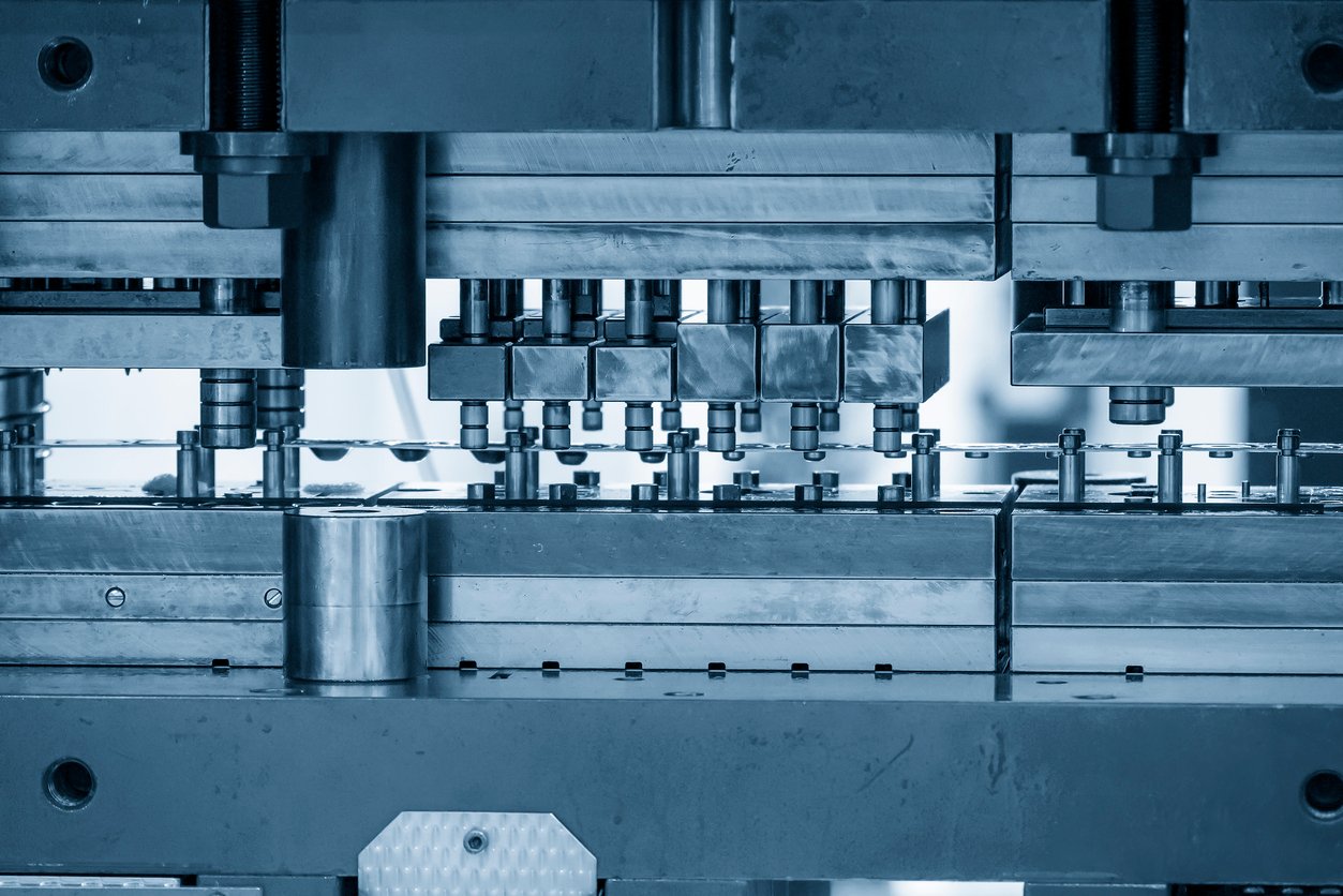
Progressive die stamping represents the apex of high-volume, automated sheet metal manufacturing. Unlike single-station transfer dies or manual secondary operations, a progressive die transforms a continuous strip or coil of flat raw metal into fully formed, high-precision three-dimensional components within a single press. The stock material feeds incrementally through a linear sequence of distinct, synchronized workstations. Each stroke of the press ram simultaneously performs cutting, punching, bending, or coining operations across multiple parts attached to a common carrier strip, culminating in a finished part blanked free at the final station.
Deploying progressive tooling requires a rigorous understanding of strip layout design, pitch control, pilot hole dynamics, side-action cam mechanisms, and sensor-based die protection systems to guarantee million-cycle tool life and dimensional repeatability.
1. Fundamental Progressive Die Architecture
A progressive die is a self-contained, highly engineered sub-system mounted inside a mechanical or servo-driven stamping press. The tool consists of upper and lower die shoes guided by precision ground pillars and linear ball cages, keeping punches and die cavities concentrically aligned within micrometers across millions of high-speed strokes.
CROSS-SECTION OF A PROGRESSIVE DIE ASSEMBLY
+———————————————–+
| Upper Die Shoe (Bolster) |
+———————–+———————–+
|
+———————-+———————-+
| Punch Retainer Plate |
+———————————————+
| Stripper Plate (Spring-Loaded) |
+=============================================+ <– Strip Guide Channel
| Die Block / Die Plate |
+———————————————+
| Lower Die Shoe (Bed) |
+———————————————–+
Core Anatomical Components
-
Upper and Lower Die Shoes: Heavy structural steel or cast-iron plates that mount directly to the press ram (upper) and press bed/bolster (lower). They distribute intense tonnage evenly across the entire tool assembly.
-
Punch Retainer Plate: Accurately holds and registers the upper cutting, forming, and piloting punches.
-
Stripper Plate: A pressure-loaded plate backed by heavy nitrogen gas springs or polyurethane dampers. It performs two critical functions: clamping the sheet strip perfectly flat against the die block before punch entry, and stripping the raw stock material off the punches as the press ram ascends.
-
Die Block (Die Matrix): The lower stationary section housing hardened tool steel or tungsten carbide die inserts, button dies, and drop-through slug clearance channels.
-
Strip Guides and Stock Lifters: Spring-loaded rails and mechanical pins that elevate the continuous metal strip off the lower die surface during the feed advance cycle, allowing three-dimensional formed features (such as downward tabs or flanges) to move forward without hitting the die blocks.
2. Strip Layout Engineering, Carrier Design, and Pitch Dynamics
The foundation of every progressive die is the strip layout. Before machining steel, tool designers map out the exact sequence of manufacturing steps on a continuous two-dimensional metal band. The strip layout balances material utilization efficiency (yield percentage) against structural rigidity and tool accessibility.
PROGRESSIVE STRIP LAYOUT AND CARRIER SEQUENCE
Feed Direction —>
+——-+——-+——-+——-+——-+——-+——-+——-+
| (o) | (x) | (x) | (x) | | | / | ( ) | [ ] | <– Carrier Web
| | | | | | | | | | | | |
| S1 | S2 | S3 | S4 | |S5 | | |S6 | | S7 | S8 | <– Part Geometry
| | | | | |___| | |___| | | |
| (o) | (x) | (x) | (x) | | | / | ( ) | [ ] | <– Carrier Web
+——-+——-+——-+——-+——-+——-+——-+——-+
Pierce Engage Notch Notch Form Form Idle Part Cutoff
Pilot Pilots Profile Profile Flange Emboss Station & Separation
Key Elements of a Progressive Strip Layout
-
Station 1: Pilot Hole Piercing: The very first station pierces precise round reference holes along the scrap margins (carrier web) of the strip.
-
Station 2: Pilot Engagement: Hardened, bullet-nosed piloting pins descend into the newly pierced holes before any subsequent tool touches the strip. These pilots correct minor mechanical feeding errors, locking the strip into exact registration ($pm 0.005 text{ mm}$) for the rest of the layout.
-
Intermediate Stations: Relief Notching and Profiling: Cutting away internal scrap regions and surrounding border metal. This isolates individual part regions while keeping them attached to the main strip via narrow, ductile metal bridges known as carrier webs.
-
Forming and Bending Stations: Bending tabs, drawing small cups, extruding thread holes, or embossing stiffening ribs. Isolating the part via relief notches allows these forming operations to draw material locally without distorting adjacent parts along the strip.
-
Idle Stations: Empty stations left intentionally unmachined to provide physical clearance for heavy tool retainers or to allow future engineering design changes (ECOs) without rebuilding the entire die set.
-
Final Station: Cutoff or Blanking: Separation punches shear the finished part free from the carrier web, dropping it down a chute or into a discharge conveyor.
Pitch and Width Calculations
-
Pitch ($P$): The exact center-to-center linear distance between two adjacent stations. The automated press feeder must advance the raw strip by precisely one pitch distance on every press stroke.
-
Strip Width ($W$): Sized to accommodate the maximum unfolded part geometry plus the required outer carrier web margins and edge clearance.
3. Side-Action Cam Mechanisms for Complex Angles
When a component requires punching, piercing, or bending at an angle perpendicular or oblique to the vertical stroke of the press ram (e.g., punching a side hole in a formed bracket), standard vertical punches cannot accomplish the feature. Progressive dies solve this using side-action cam mechanisms.
MECHANICS OF A MECHANICAL DIE CAM SLIDE
Press Ram Descending (Vertical Motion)
|
v
+—————+
| Driver / Wedge| (Angled Heel Block)
+——/ ——-+
/
/ <– Incline Plane Transition
/
+————-+—–> Horizontal Tool Motion
| Cam Slide | [Punch] ===> Metal Workpiece
+————-+
| Coil Spring | <– Retracts slide on upstroke
+————-+
Operational Sequence of a Die Cam
-
Vertical-to-Horizontal Conversion: As the press ram descends, a hardened wedge (the cam driver) mounted on the upper shoe contacts an inclined slide block (the cam slider) sitting on the lower shoe.
-
Transverse Tool Engagement: The angled interface translates vertical downward force into a smooth, high-tonnage horizontal or angled stroke, driving the side punch directly into the standing sidewall of the workpiece.
-
Positive Return: As the press ram ascends, mechanical return springs (or nitrogen actuators) push the cam slider back to its home position, retracting the side punch safely out of the part before the strip advances to the next pitch.
4. Advanced Die Protection, In-Die Sensing, and Quality Automation
Operating a complex, multi-station progressive die at speeds between 100 and 1,000+ strokes per minute poses severe financial risk if a failure occurs. A single stuck slug, misfed strip, or broken punch can cause hundreds of tons of press force to smash onto jammed steel, instantly destroying a $250,000 tooling investment. Modern progressive dies utilize integrated in-die electronic sensor networks wired directly into the press emergency stop circuit:
IN-DIE SENSOR NETWORK SCHEMATIC
+———————–+ +———————–+ +———————–+
| End-of-Feed Sensor | | Pilot Pin Proximity | | Slug Inspection |
| (Optical / Laser) | | (Inductive Sensor) | | (Photoelectric) |
+———–+———–+ +———–+———–+ +———–+———–+
| | |
+———————-+——+———————-+——+
|
v
+—————————+
| Press Safety Controller |
+————-+————-+
| Emergency Hydraulic Stop
v
+—————————+
| Press Clutch & Brake Unit |
+—————————+
-
Feed Misfeed Sensors: Optical or proximity sensors verify that the raw material strip has advanced by the exact required pitch ($P$) before the upper die contacts the metal. If the strip stops short, the press halts instantly.
-
Pilot Protection Sensors: Inductive sensors mounted above the spring-loaded pilot pins detect whether a pilot pin fails to enter its alignment hole cleanly (e.g., if the strip buckled).
-
Slug Detection Sensors: Photoelectric light curtains mounted beneath the lower die block verify that every blanked steel slug drops through the relief channels. Trapped slugs that double-stack under punches cause catastrophic tool cracking.
-
In-Die Quality Measurement (LVDTs): High-precision Linear Variable Differential Transformers measure critical bend angles, draw depths, and material thicknesses in real time, automatically halting production if tolerances drift outside defined statistical process control (SPC) limits.
5. Tool Steel Metallurgy and Surface Engineering
Progressive die components endure millions of high-impact cycle loads and continuous abrasive friction against raw sheet steel. Maximizing tool longevity requires matching tool steel alloys and chemical surface treatments to specific operational stress zones:
|
Tooling Component |
Common Tool Steel Grades |
Hardness (HRC) |
Surface Treatment / Coating |
Primary Function |
|
Die Shoes / Bolsters |
AISI A36 Structural Steel, Cast Iron |
Non-hardened |
Oxide Coating |
Heavy structural frame, vibration damping. |
|
Blanking & Piercing Punches |
AISI D2, A2, High-Speed Steel (M2) |
58–62 HRC |
TiN / TiAlN PVD Coating |
Extreme wear resistance, clean fracture edge control. |
|
Severe Impact Punches |
AISI S7 (Shock-Resisting Steel) |
54–58 HRC |
Nitriding |
Resists chipping and fatigue cracking under high shock loads. |
|
Deep Drawing & Forming Inserts |
Tungsten Carbide (WC-Co), AISI D2 |
62–68 HRC |
CVD Diamond / CrN Coating |
Eliminates surface galling, scuffing, and metal pick-up. |
Summary
Progressive die stamping delivers high efficiency, tight dimensional tolerances, and low unit costs for volume sheet metal production. Success relies on robust mechanical architecture, detailed strip layout design, precise pilot alignment, and side-action cam integration. By pairing hardened tool steels and PVD/CVD coatings with real-time in-die safety sensors, manufacturers produce millions of complex parts with minimal downtime.
Stainless steel pipes kampala uganda
